
Measuring assembly for thickness measurement
Three basic layouts are offered depending on the implemented method.
1. One-sided thickness measurement against a reference
The respective sensor is arranged here above the material and measures against a reference which is below the material. This reference may be either a fixed plate or a roller over which the material is moved. The sensor is zeroed against the reference and then measures the fed material. The difference is the thickness. It is important that the material has contact with the reference throughout the measurement be- cause otherwise an incorrect thickness will be measured due to an air gap or mate- rial deposited on the reference. The reference roller has therefore established itself for practical purposes. The touching of the material is guaranteed by the looping angle. The concentricity error of the roller must be much smaller than the required measuring accuracy to receive reliable values.
2. Two-sided thickness measurement
By arranging one sensor above and one below the measuring medium the thick- ness measurement is made as a difference measurement. Each sensor measures the distance from the material. Subtracting both measured values from the cali- brated basic distance of the sensors gives us the thickness. Since both sensors operate absolutely in synchronisation, a vertical movement of the measuring medi- um (e.g. due to vibrations or roller errors) does not cause an error in the thickness measurement. The calibration of the measurement layout is slightly more com- plicated.
It can be done manually by measuring a target of known thickness to give the basic distance from the individual measured values of the sensors plus target thickness. But it can also be done automatically by swinging in a reference target in the absence of a measuring medium. In this arrangement it is important to have a sturdy measuring frame, designed as a C or O frame so that the distance between the sensors does not change during the measurement. Basically the measurement can be performed as a single or multi-track measurement.
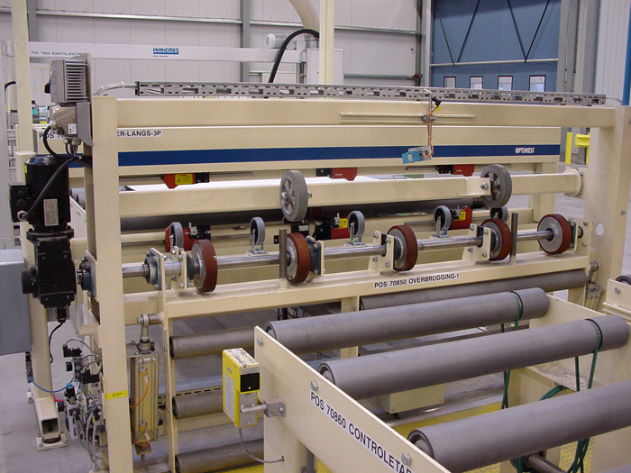
3. Traversing thickness measurement
If a thickness measurement is desired not only in individual tracks but over the whole material width, a traversing thickness measurement can be used. Here, like in the single track measurement, one sensor is mounted above the material and measured against a reference or the thickness is measured with two sensors above and below the material with the difference that the sensors are mounted on a linear guide. The upper and lower sensors are coupled by a common drive so that they can be moved in synch. Traversing widths of more than 5 m can be covered in this way.
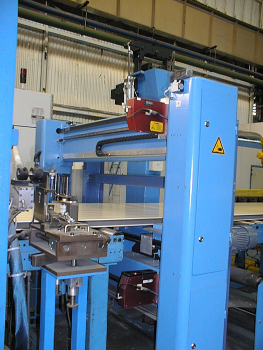
A zigzag measuring line is produced on the material when the product is trans- ported through the system and the sensors are traversing. A transverse and longi- tudinal profile of the material thickness can be derived from this in the further processing software. Since the vertical guidance errors of the linear guides are included directly in the thickness, a so-called traverse error correction must be recorded prior to the measurement, saved in the software and corrected later with the recorded measured values at the respective measuring position. With the OPTImess, UDM and DMS systems described here it is possible to manufacture customised thickness measurement systems as tactile or non-contact systems for almost all materials and temperatures as single track or multi-track systems or traversing systems.