
Even Surface Measurement
An important quality feature of sheet metal is its evenness. Irregular stretching of the sheet metal during rolling, due to discrepancies in switch gap geometry, is the reason for evenness faults in the sheet metal. For evenness optimising, measuring and control systems are integral parts of rolling mills.For the monitoring of these plants, extremely accurate evenness measurements are necessary. Therefore, an evenness measuring table for off-line determination of even surface on ready-made steel band samples was developed by a major steel manufacturer.
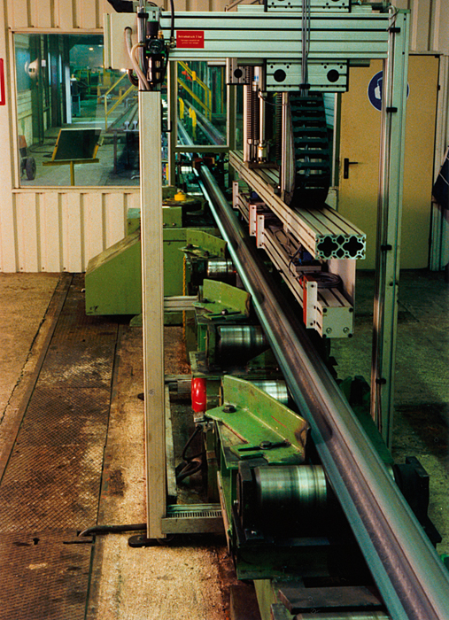
The edge and centre waviness is to be detected by this device. For this purpose a cut-out sheet sample is placed on the measuring table. The altitudinal profile of the sheet metal is scanned by means of a measuring frame, which is equipped with seven OPTImess laser sensors. The band length for each measuring track is determined by a mathematical algorithm on basis of the height values. In consistency measurements the maximum fault range in 40 measurements was 1.5 I-units. The system's theoretical resolution is +/- 0.65 I-units.
This kind of evenness measurements in production can also be carried out by non contact laser technique. Tests at major steel manufacturers' have indicated that the altitudinal profile can also be registered at high production speed, due to the wide band width of the OPTImess sensors of up to 10 kHz. As all kinds of waves, from those passing through at production speed to static waves and all intermediate types, can occur during the production process, an in-line arrangement of several sensors is necessary. Number and distance between the sensors depend on the length and type of wave which is to be measured.
An evenness measuring system with a specific software for the mathematical calculation has been realised for measurements at high-speed railtracks. The objective has been the exact localisation of the maximum and minimum values of the railtrack's travelling surface. For this, a known reference length is to be moved along the railtracks's travelling surface, similar to the measurement by hand with a 3-mtr ruler. The distance to this length is calculated for an individual point at a time. The occurring discrepancies in amplitude and phase, which depend on the measuring length L, have not been counteracted, as was common practice before, by increasing the number of detectors or by optimising the distances between the detectors. Distortion correction of the measurement graph is, instead, effected by Fourier transformation with correction of the amplitude and phase characteristics. This correction is a close approximation of the surface functional analysis. For correcting shorter wave lengths a second reference length is introduced.
The total result is reached by combining both correction processes.p> Since then, an automatic 100%-control of production is being carried out with the measuring system described above. The total measuring process runs fully automatic in several steps. For the setting of the whole plant only the railtrack profile is required, apart from operational data. Due to the special algorithms, the system is largely insensitive to the rollers' eccentricities and the rail's self-vibrations. With the help of this system minimum and maximum values with an accuracy of 0.1mtr can be localised. In trough calculation maximum discrepancies of 0.05mm occur compared to manual measurements.
The system's flexibility allows for extensions in several directions. Acceleration can be effected either by a larger number of sensors or by extending the spectral range.